
Invert Gravel Volume Change Instructions
Jun 2025 orig., Jan 2026 rev.
Recommendations and Warnings
Cane Creek recommends only trained suspension technicians perform service on all suspension, using all required tools and following all proper procedures. Anyone without access to the proper equipment or with any concerns on the procedures should defer to an authorized Cane Creek service center for service. Improper service can result in loss of performance or suspension failure. Follow the service procedures exactly as written to avoid possible injury or harm to the suspension. Always wear eye protection while performing suspension service. Please dispose of all waste products and materials through proper channels to avoid contamination of the environment.
Any damage or issues resulting from improper service will not be covered by warranty. If you have a fork still in its original warranty period and do not wish to void your warranty, please contact an authorized Cane Creek service center.
Service Notes
These instructions cover volume change for the air spring only on a new fork. They leave out all mention of removal and discarding of standard wear parts that would be replaced as part of a 100, 200 and/or 400 hour service. If doing any of those services, please refer to those service instructions for complete steps and be sure to sure those service kits.
These instructions cover the SL & CS variants as the air spring side is virtually the same for both. Additionally, some photos reflect the seal head and wiper completely removed from the air spring leg, but this is not necessary for just a volume change.
Service Kit
No service kits required. If decreasing volume you will need one or two (max) volume reducers:
ABG0323 - Invert Gravel Air Spring Volume Reducer
Required Cane Creek Tools
None
Additional Tools & Supplies
Open 12 Notch x 46mm (BSA30) Bottom Bracket Wrench
Allen wrenches - non-ball end 4 & 6mm
8mm shaft clamp
12mm open box wrench
24mm crowfoot
Torque wrench
Knipex pliers
Picks - L-bend & straight
Oil fill syringe
Suspension Grease
Motorex 15wt Racing Fork Oil
Torque, Loctite & Oil Specs
Torque & Loctite Chart
| Part | Torque Spec | Loctite Spec | Oil Spec | Nitrogen Spec |
|---|---|---|---|---|
| Volume Reducer | Snug | None | — | — |
| Air Seal Head | 5 Nm | 243 (Blue) | — | — |
| Air Shaft Bolt | 5 Nm | 243 (Blue) | — | — |
| Lower Seal Head | 15 Nm | None | — | — |
Oil Chart
| Oil Location | Oil Type | Oil Amount | Oil Spec | Nitrogen Spec |
|---|---|---|---|---|
| Spring Side | Motorex 15wt Racing Fork Oil | 10 mL | — | — |
Related Technical Service Bulletins
Review all related TSBs before performing any service.
No specific Invert Gravel service TSBs at this time.
It is recommended that this volume change procedure be performed by professional suspension service technicians ONLY. Rapid depressurization of the air spring can occur.
General Prep
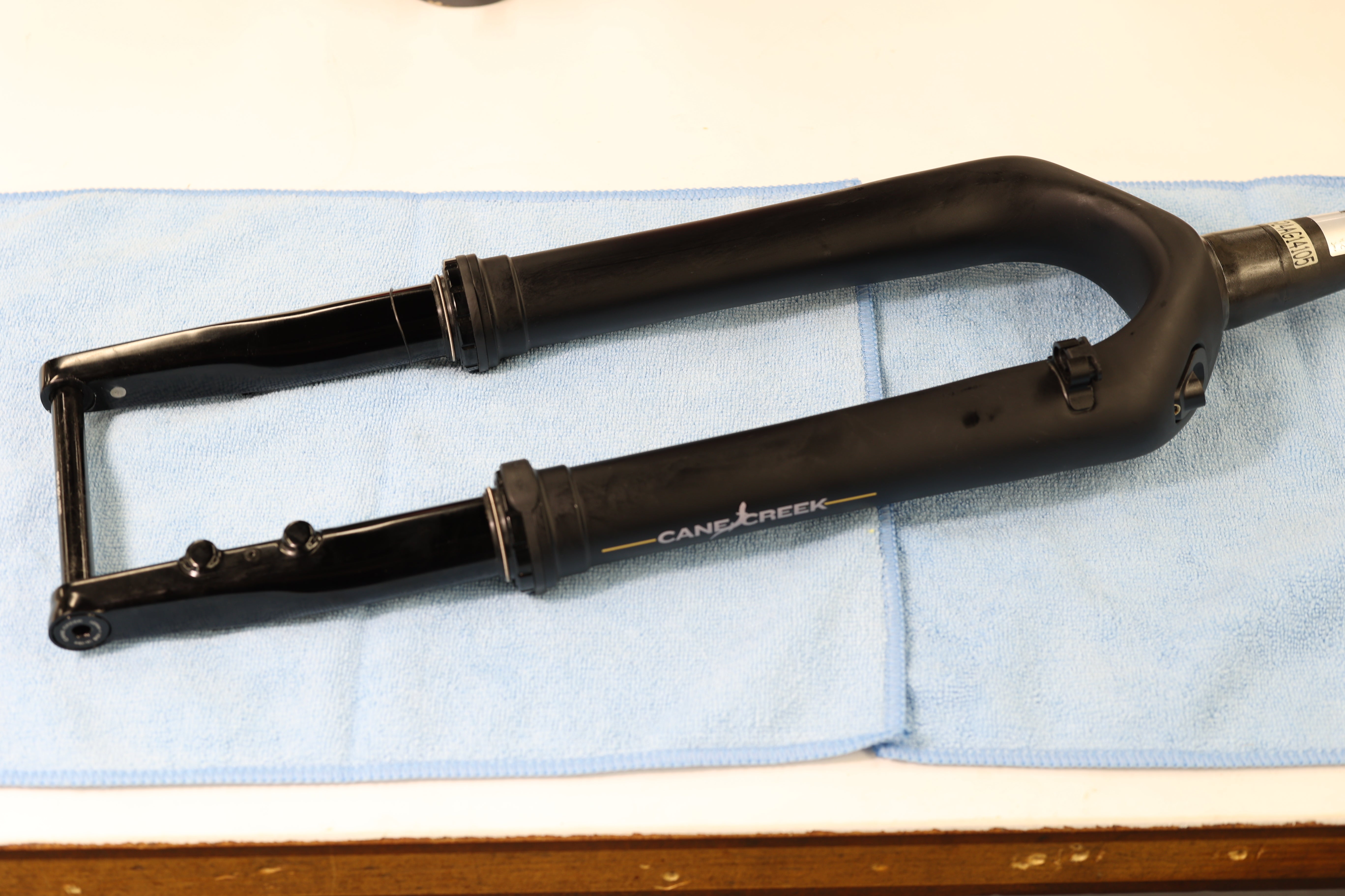
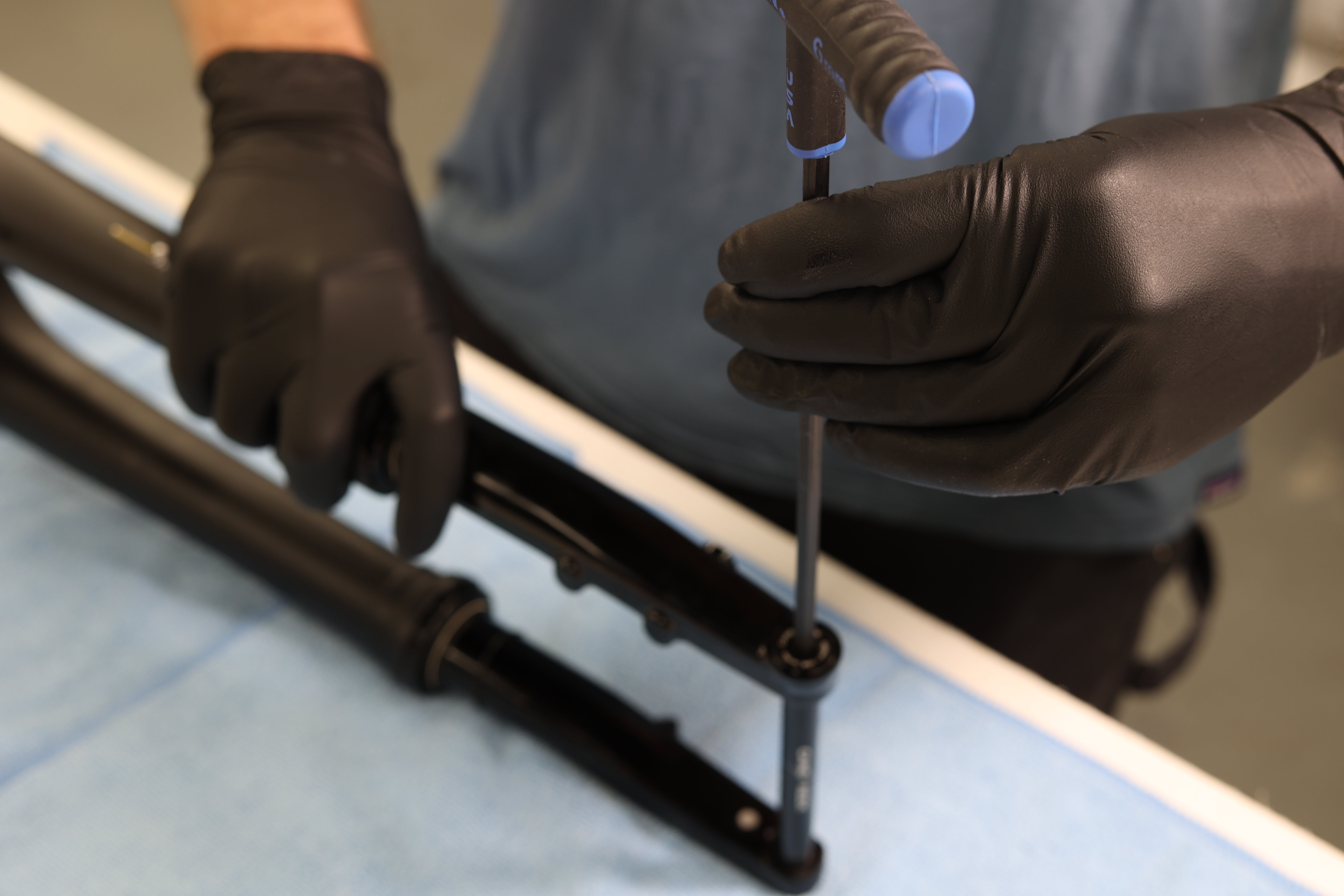
Clean fork. Inspect fork for any damage. Particularly scratches on legs. Remove axle if installed.
Fork Inspection
Axle Removal
Air Leg Removal

Step 1 – Draining Leg Oil
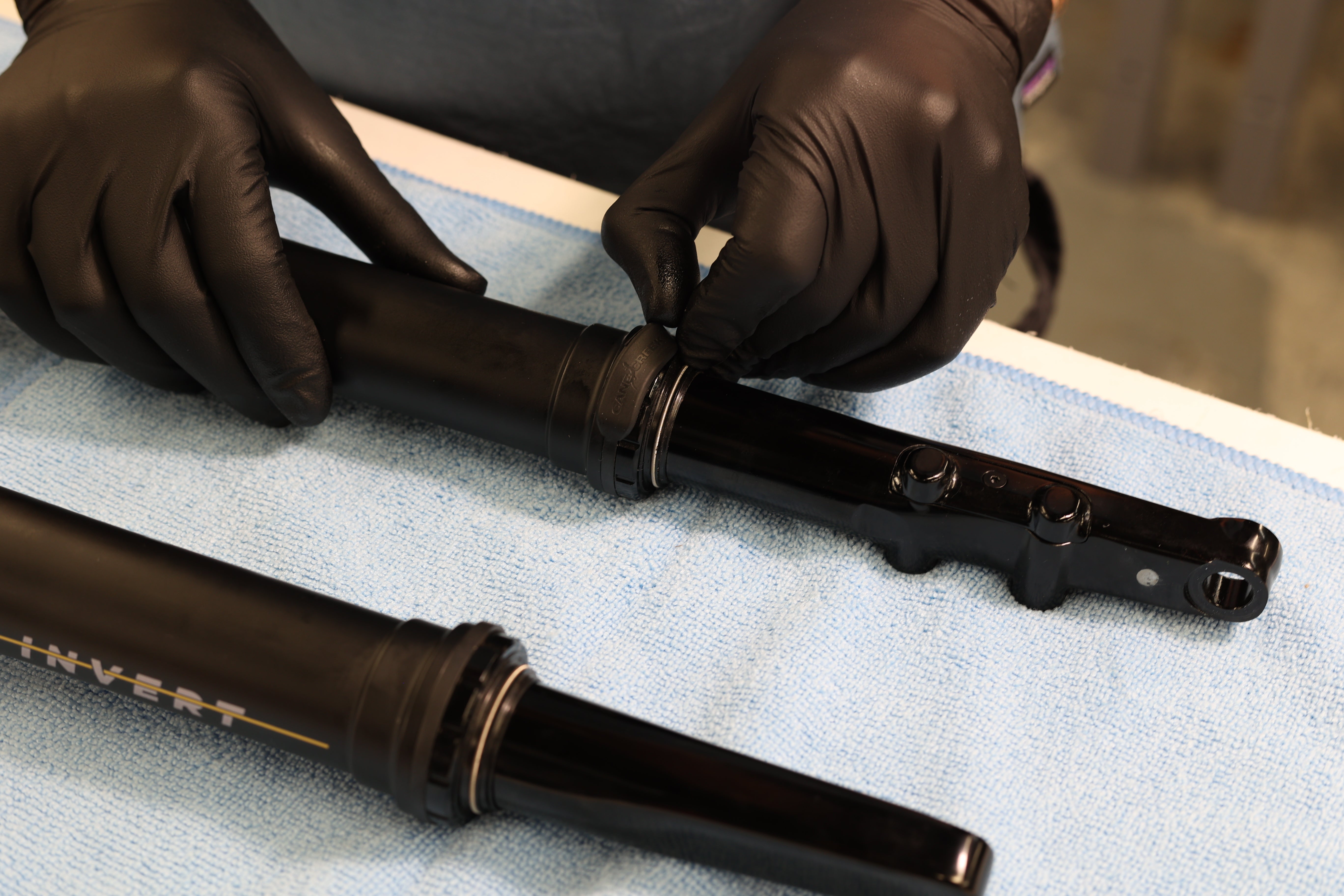
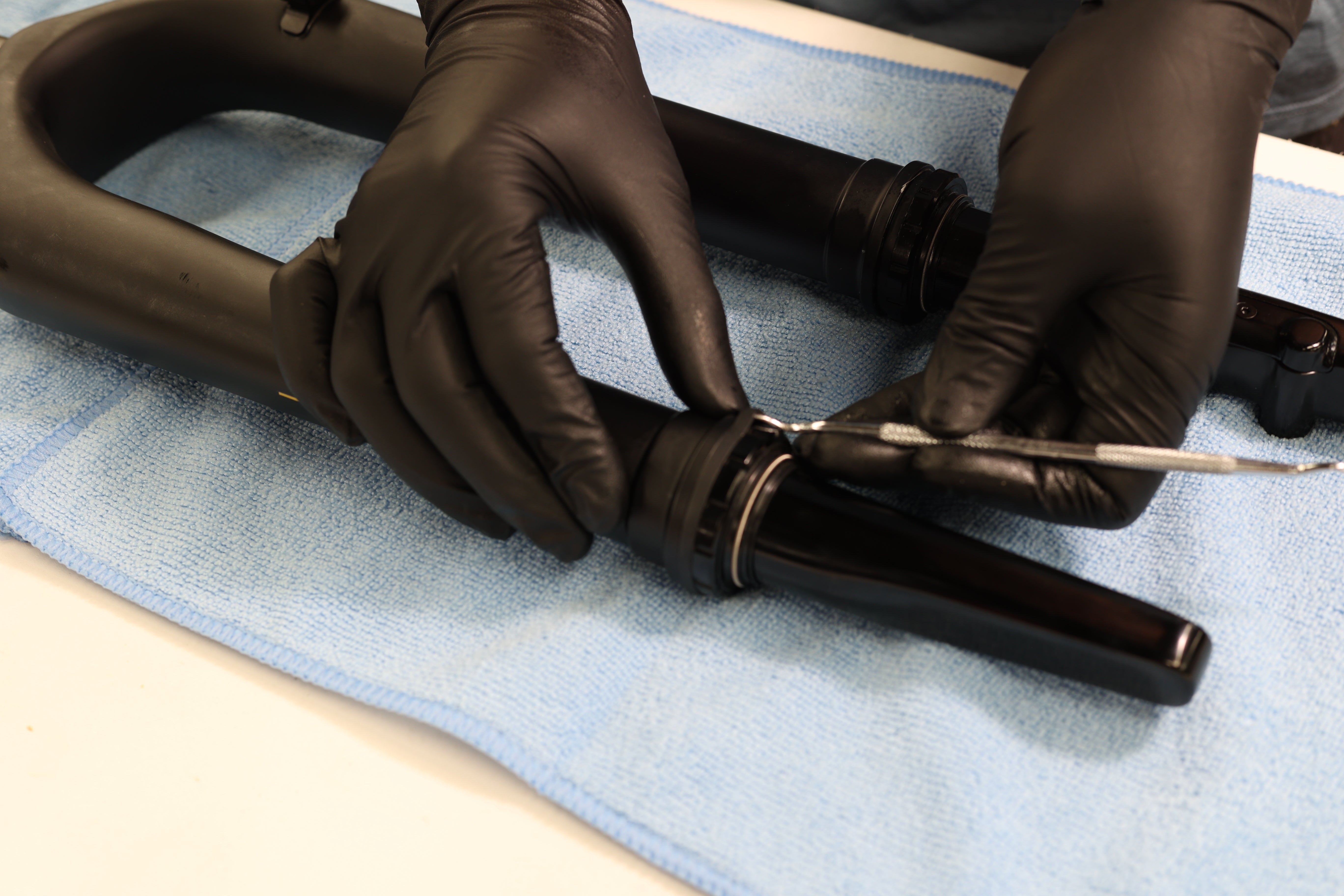
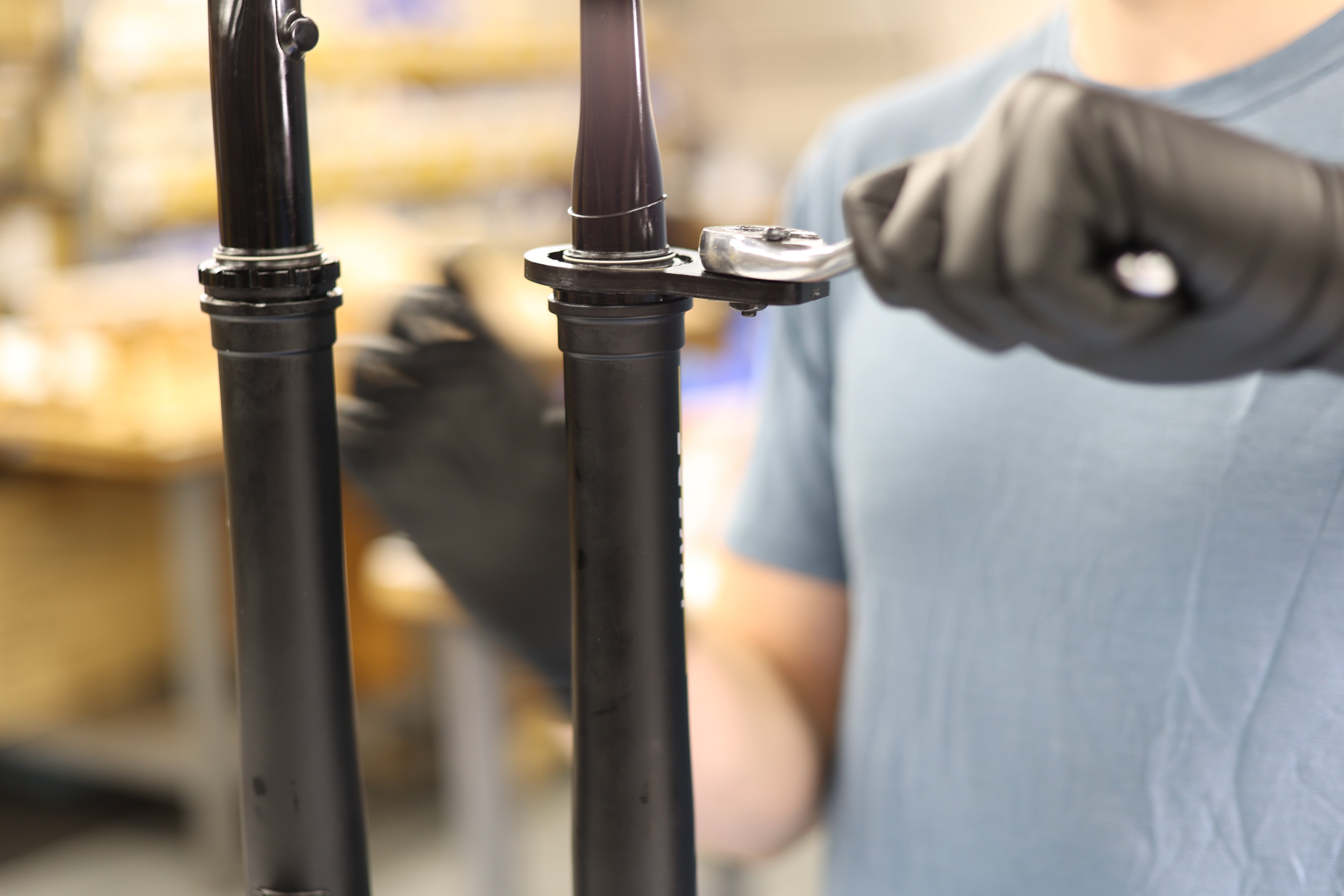
Remove seal head guard. Use pick if necessary. With fork inverted to prevent oil loss, loosen lower seal head on AIR SPRING SIDE ONLY using Bottom Bracket Wrench or strap wrench. Back seal head all the way off and dump splash oil. Dispose of oil properly.
Brake Side Seal Head Guard Removal
Spring Side Seal Head Guard Removal
Freeing Spring Side Seal Head
Draining Leg Oil


Step 2 – Air Spring Side Leg Removal
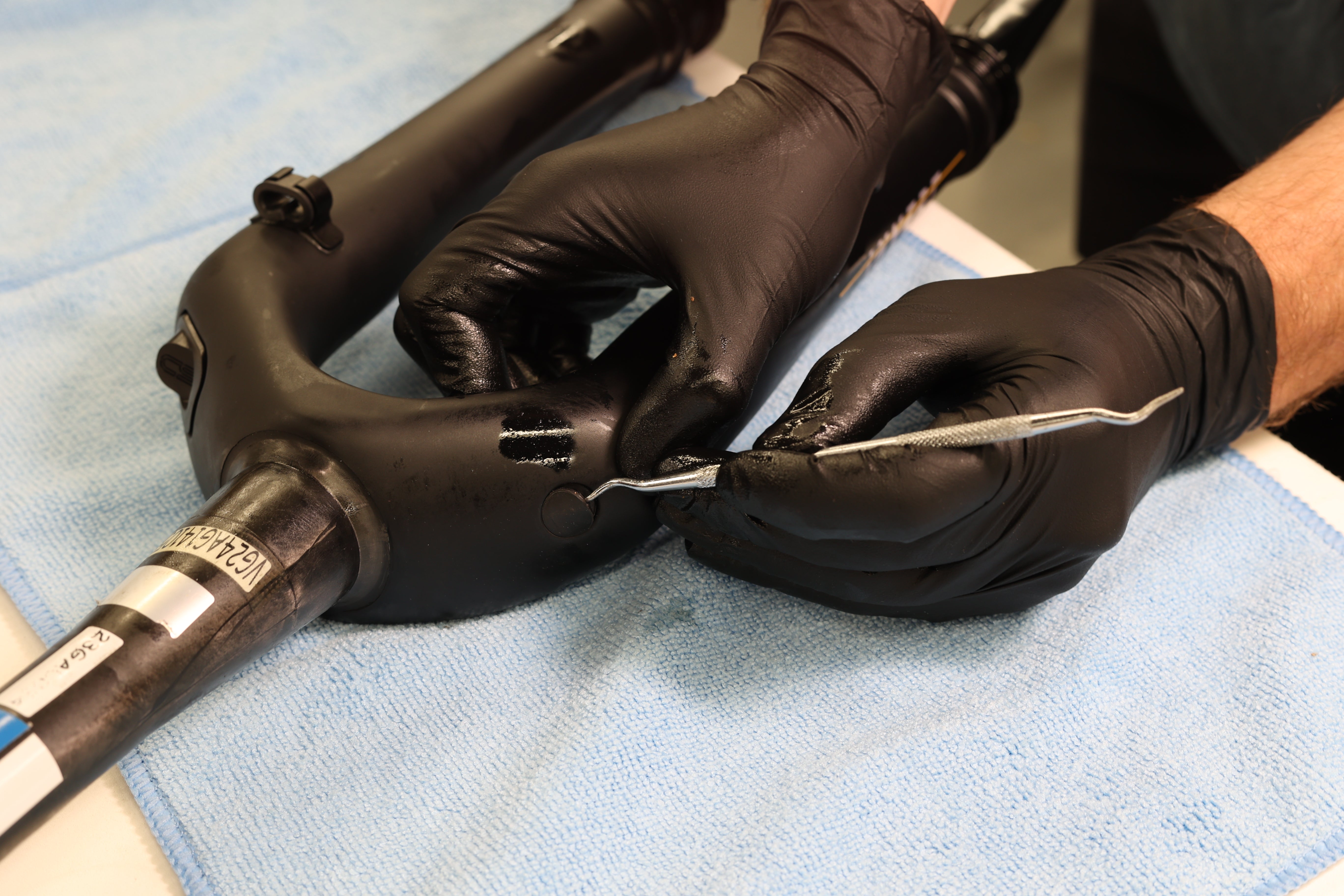
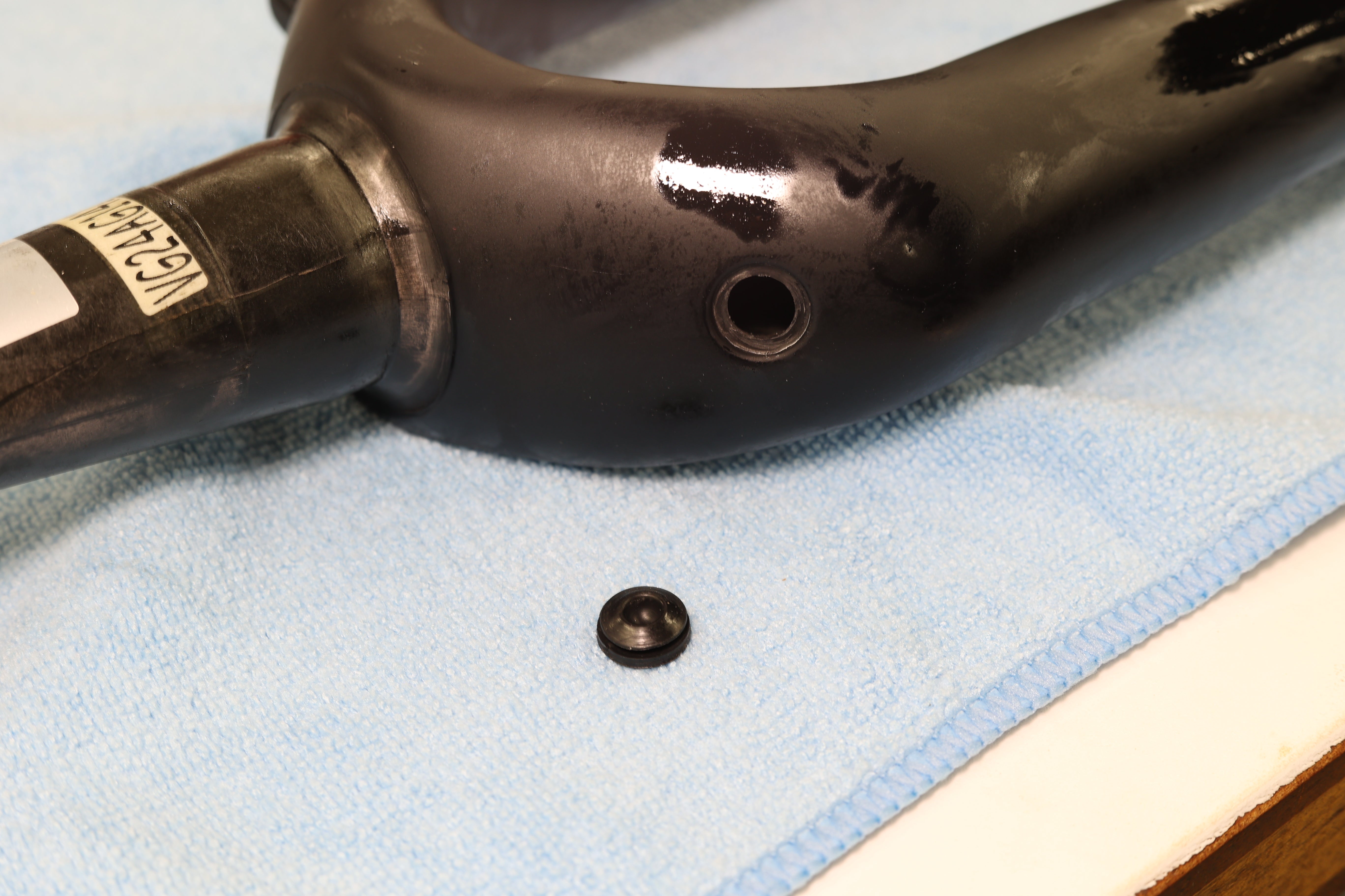
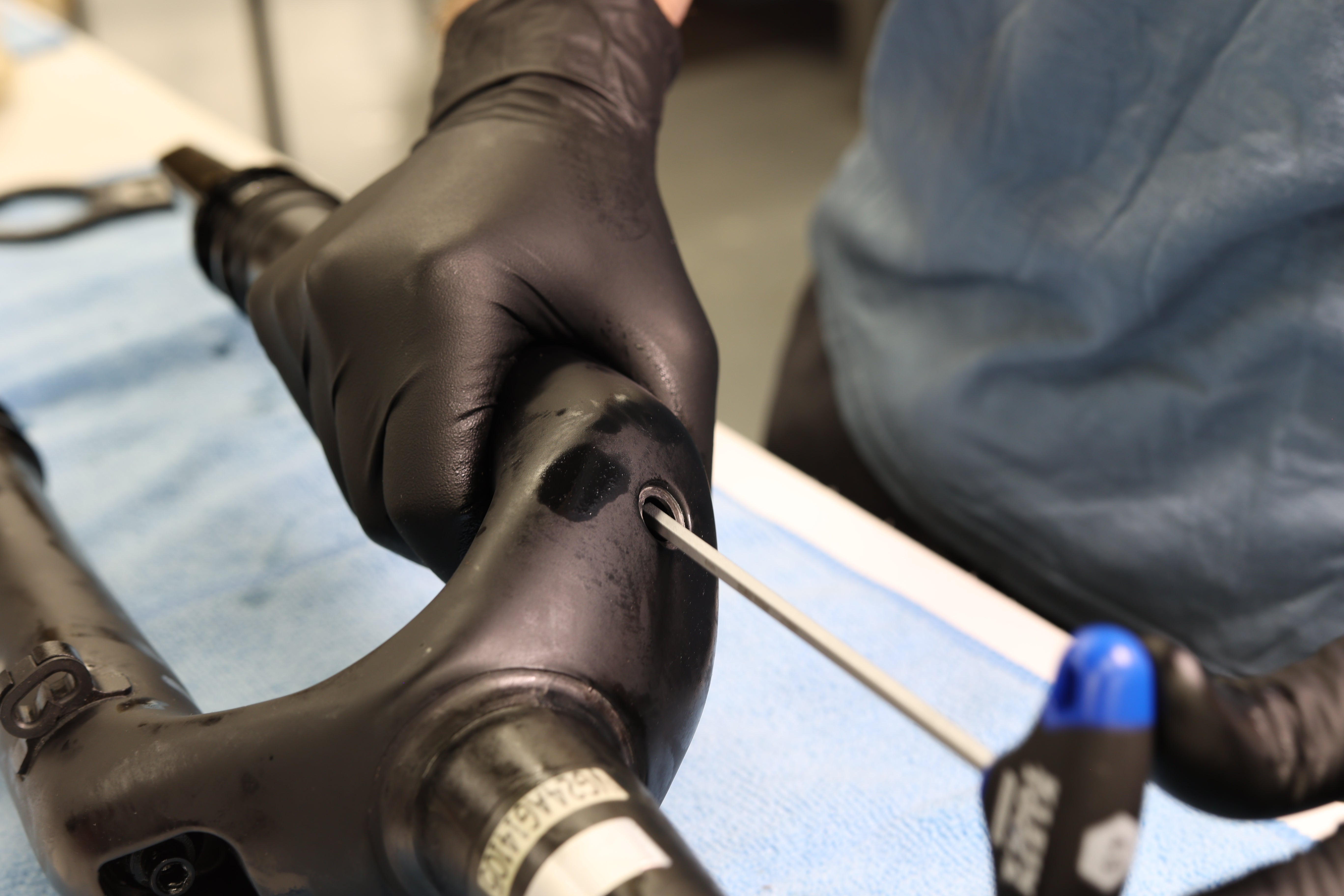
Using pick, remove air side plug on top of fork upper. Using non-ball end 4mm Allen, loosen air shaft nut until completely disengaged. Nut is contained within upper. Remove air spring leg. Remove air cap and bleed all air from air spring.
Air Side Plug Removal
Air Side Plug Removed
Freeing Air Shaft
Air Leg Removal
Air Leg Removed
Bleeding Air
Air Spring Disassembly


Step 1 – Upper Bushing Removal
Using pick, remove upper bushing. Take care to not overexpand bushing as it will be reinstalled.
Freeing Bushing
Pushing Bushing Off Leg


Step 2 – Circlip Retaining Puck Removal
Clamp shaft in 8mm shaft clamp, allowing space to access seal head. Using 12mm box wrench on air seal head nut and Knipex on circlip retaining puck flats, free retaining puck from seal head. Fully unthread retaining puck while clamped to capture the seal head in the event of residual air pressure. Once circlip retaining puck is completely free, unclamp shaft and remove puck completely.
Shaft Clamped
Freeing Circlip Retaining Puck
Unthreading Circlip Retaining Puck
Circlip Retaining Puck Removed


Step 3 – Seal Head Circlip Removal
***Use extreme caution as negative air chamber may have residual pressure. Releasing circlip can cause rapid depressurization***
Reclamp shaft into vice. Locate circlip access hole. Wedge L-pick underneath circlip and hold in place. With secondary pick, pry circlip free. Take care to keep fingers away from circlip in the event of residual air pressure. Keeping L-pick in access hole, remove circlip while keeping seal head secured in place.
Clamping Shaft
Inserting L-pick into Circlip Access Hole
Securing L-pick in Circlip Access Hole
Freeing Circlip
Circlip Removal
Circlip Removed


Step 4 – Air Spring Removal
***Use caution as negative air chamber may have residual pressure.***
With shaft still firmly clamped, pull down on leg to remove from air shaft assembly. Use of Knipex on seal head nut flats to aid removal by twisting may be necessary.
Pulling Down on Leg
Knipex on Seal Head Nut
Leg Removal
Leg Removed


Step 5 – Volume Reducer Install/Removal
Stock air spring has a single volume reducer installed on end of piston. Maximum number is three. Not recommended to run zero reducers.
To add reduction, thread new volume reducer (ABG0323) onto original reducer. Using Knipex, tighten to snug.
To remove reduction, use Knipex to free and then remove volume reducer.
Stock Air Spring with Single Volume Reducer Installed
Volume Reducer Uninstalled
Volume Reducer Install/Removal
Volume Reducer Freeing/Tightening
Air Spring Reassembly


Step 1 - Air Spring Install
Lightly grease piston & quad ring and seal head & o-ring. Insert air spring assembly into air leg. Rotation and wiggling will aid install. Apply pressure on seal head nut until fully seated. If necessary, use 8mm shaft clamp as surface to apply pressure. Seal head will click into place when seated.
Greasing Rings
Air Spring Install
Air Spring Install w/ Aid of Shaft Clamp
Air Spring Installed


Step 2 - Seal Head Circlip Install
Align circlip so one end is behind access hole. Install circlip into leg, securing air spring assembly. Using pick, follow circlip all the way around to ensure it is fully seated.
Properly Align Circlip
Circlip Install


Step 3 - Circlip Retaining Puck Install
Apply 243 (Blue) Loctite to seal head threads. Install circlip retaining puck and thread into place. Clamp shaft. Using 12mm box wrench on seal head flats and 24mm crowfoot on circlip retaining puck, torque to 5 Nm.
Applying Loctite to Seal Head
Circlip Retaining Puck Install
Shaft Clamped
Torquing Circlip Retaining Puck

Step 4 - Upper Bushing Install
Precompress bushing and install on air spring leg.
Torquing Circlip Retaining Puck
Air Leg Install


Step 1 – Spring Side Leg Install
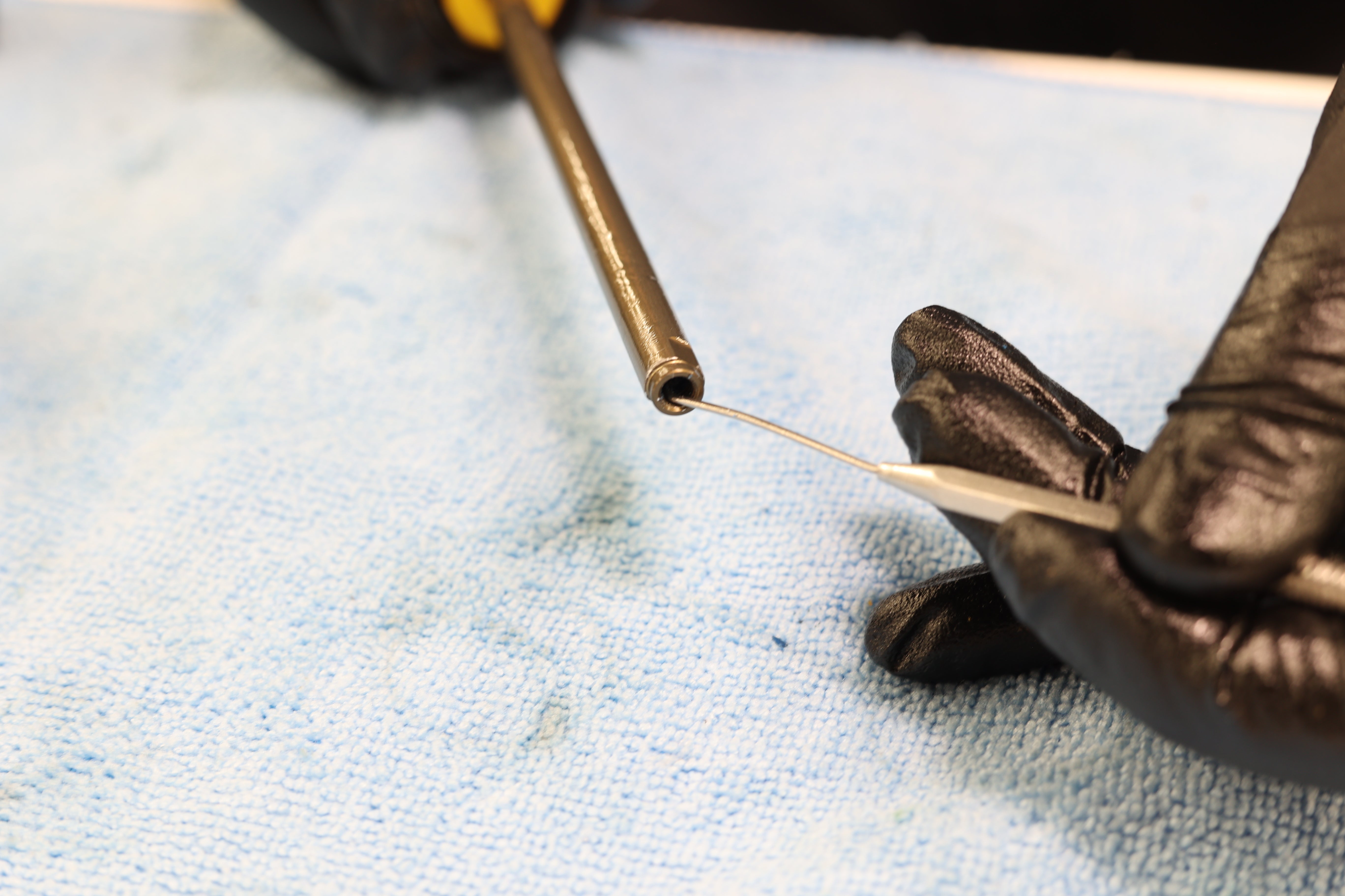
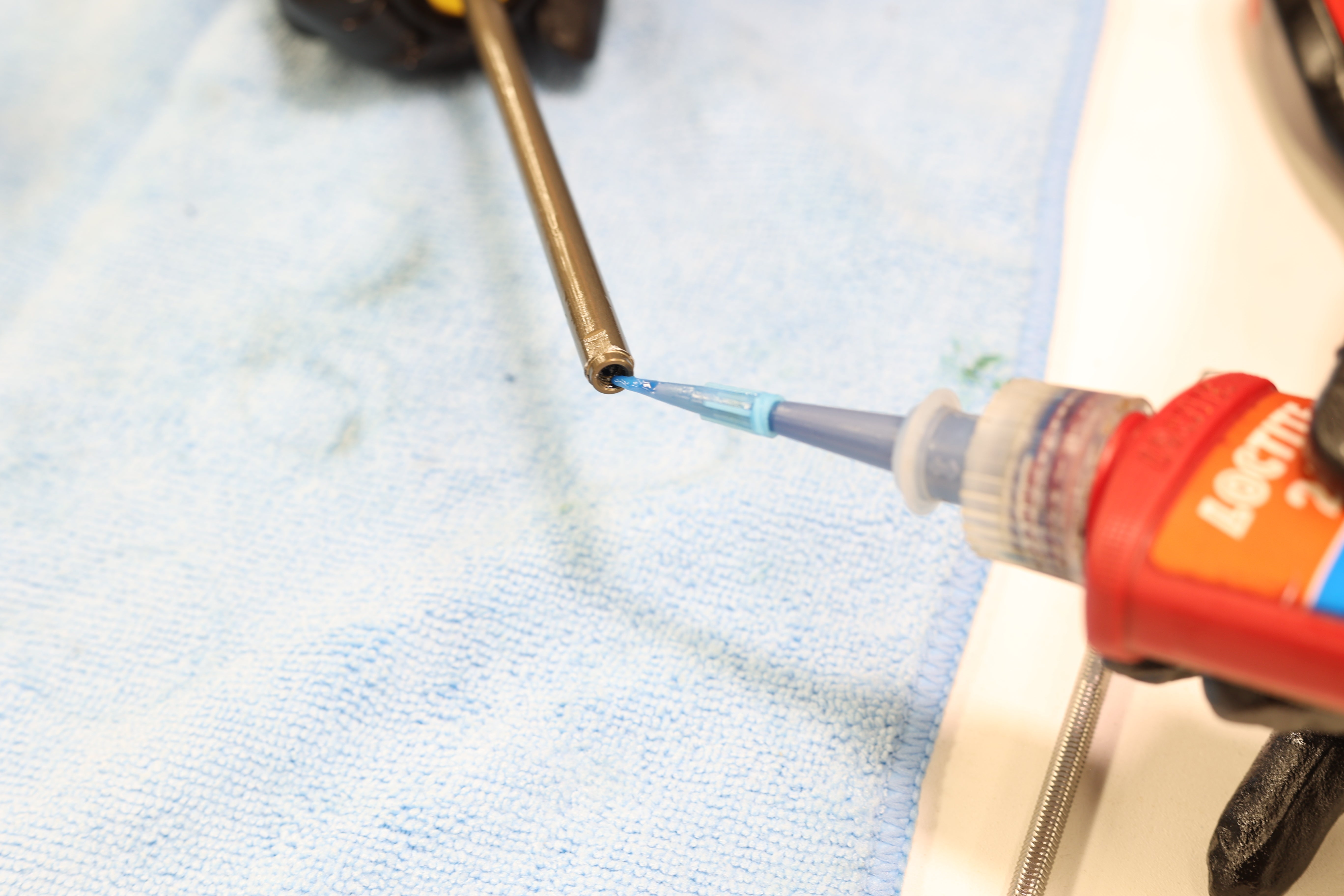
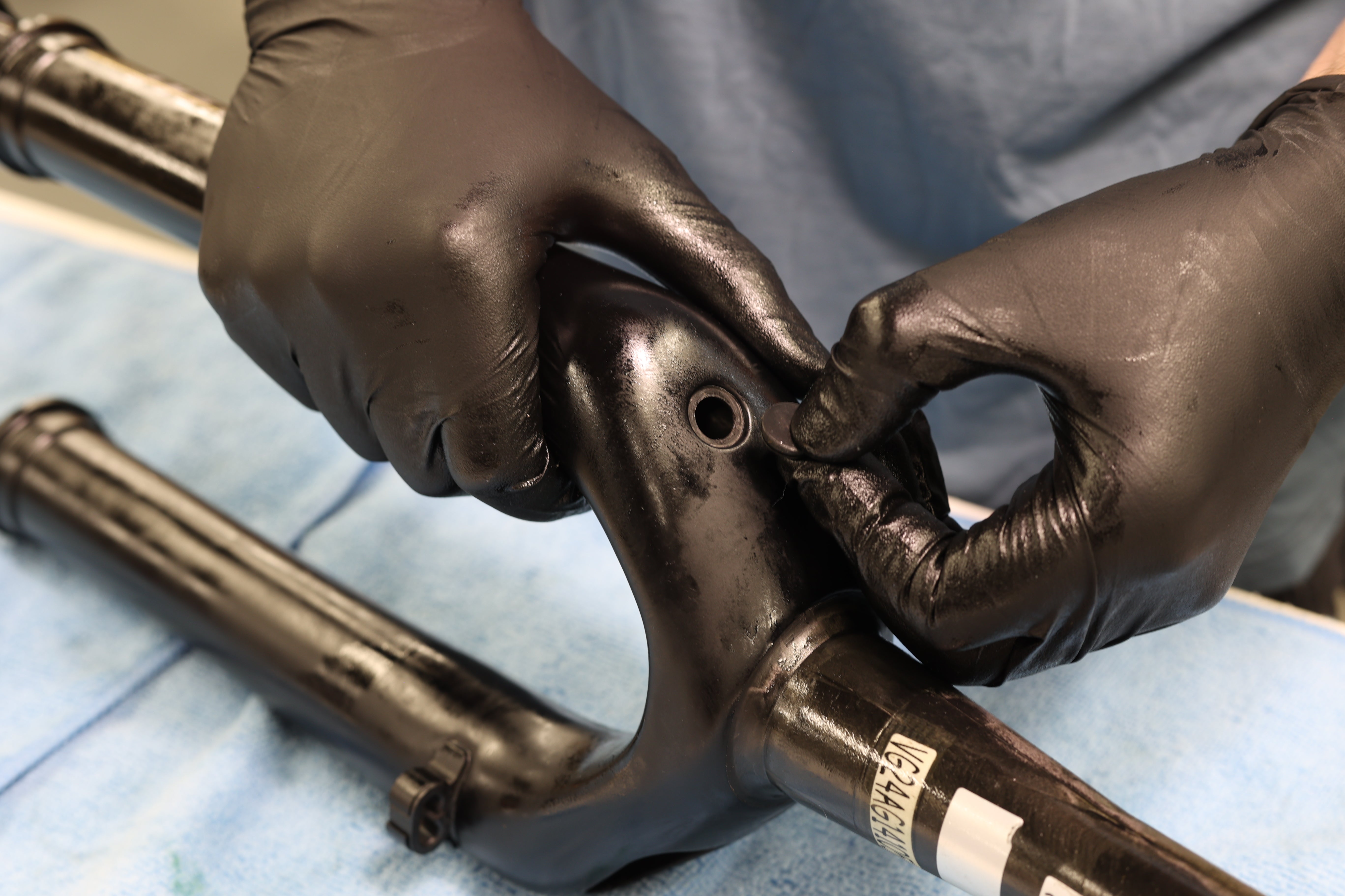
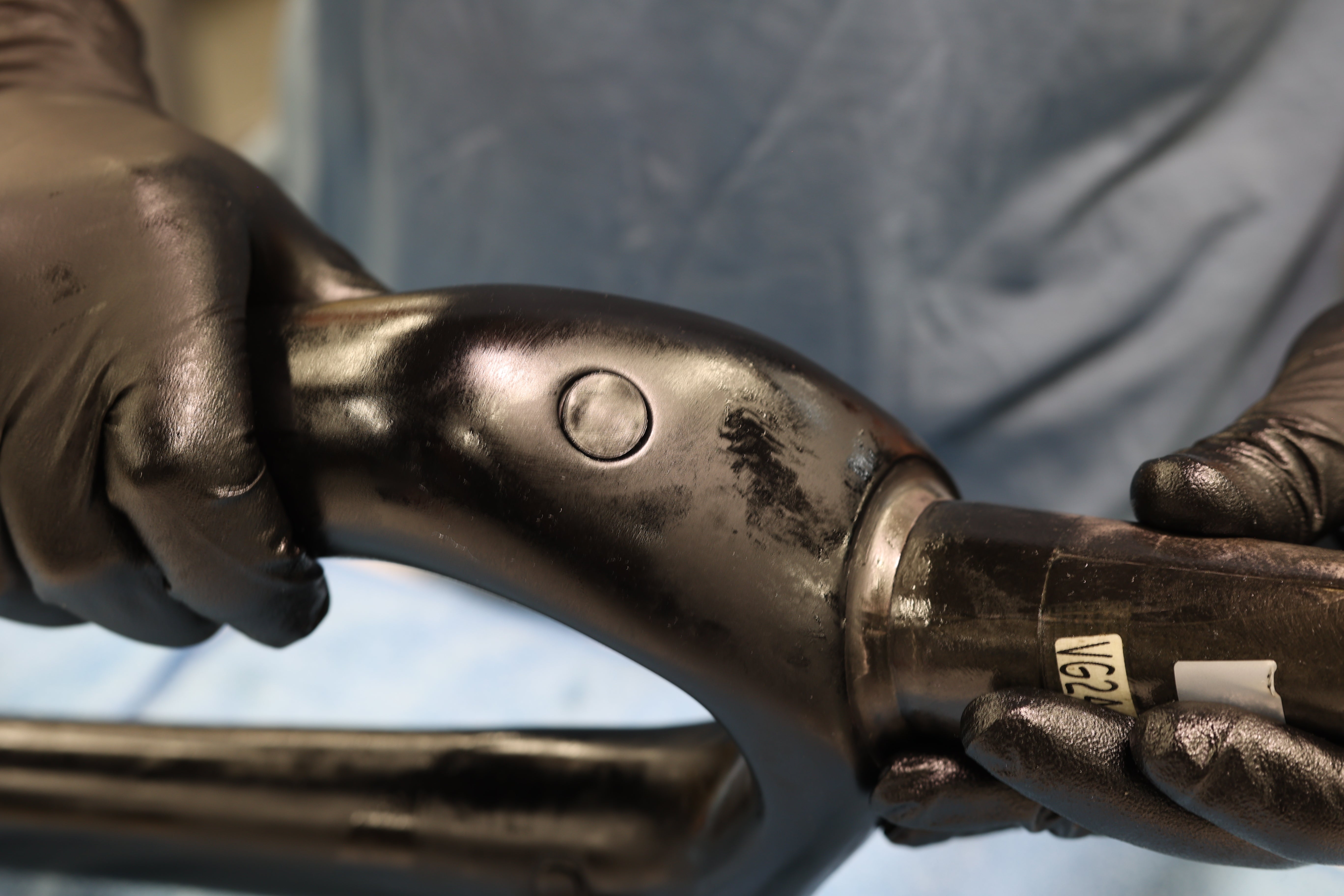
Clean threads on air shaft with pick. Apply fresh 243 (Blue) Loctite to shaft threads. While pinching bushing, insert air leg into air side of fork upper. Gently slide leg into upper until first contact with shaft and fork upper. While gently applying pressure, rotate air leg assembly until you feel the flats on the air shaft slot into place. Maintain pressure to keep shaft engaged. Using non-ball end 4mm Allen, thread air shaft bolt onto air shaft through fork upper. Torque to 5 Nm. Reinstall air side plug on uppers.
Cleaning Air Shaft Threads
Applying Loctite to Air Shaft Threads
Pinching Bushing for Install
Spring Side Leg Install
Spring Side Leg Installed
Air Shaft Bolt Torque
Air Side Plug Install
Air Side Plug Installed
Step 2 – Adding Leg Oil
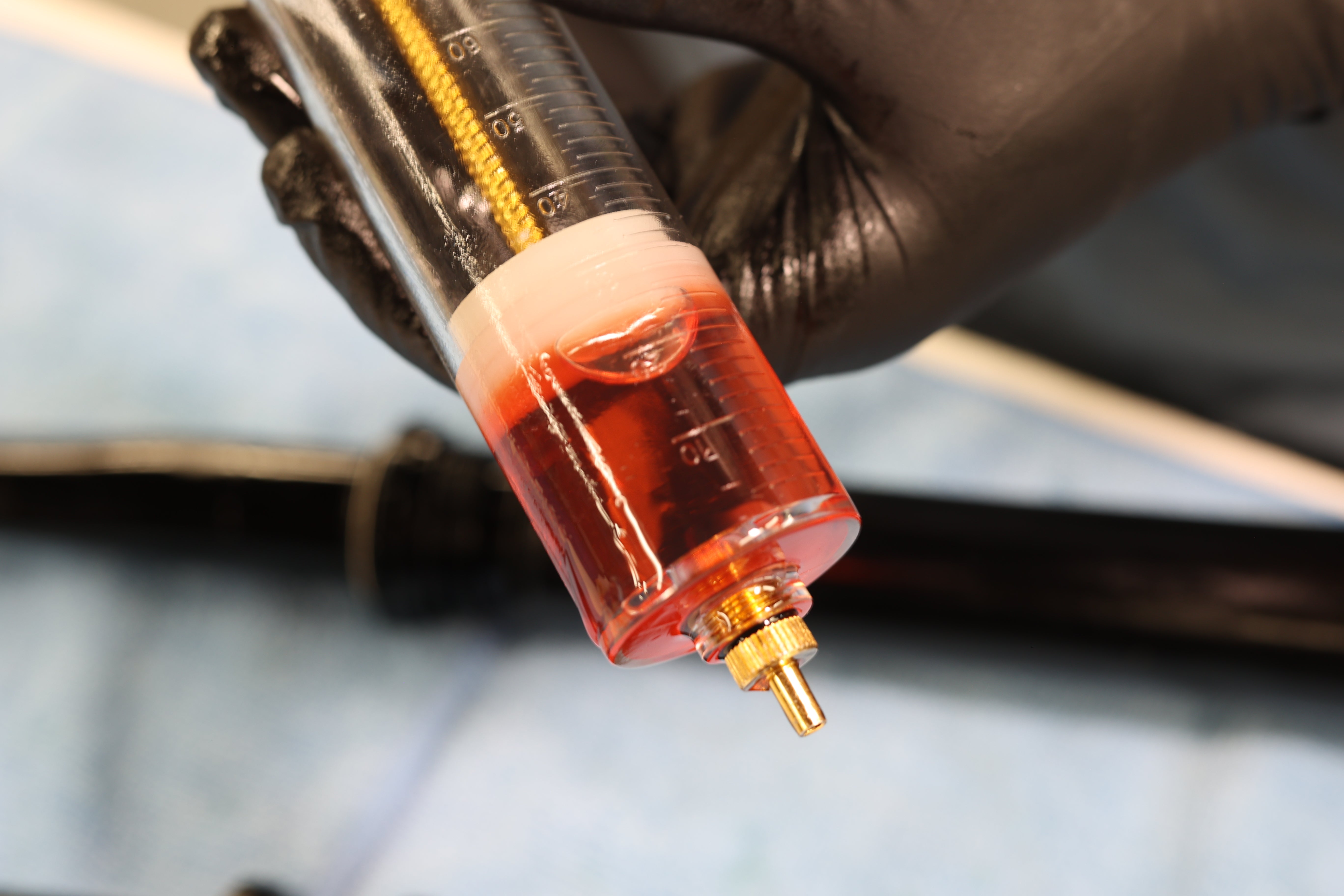
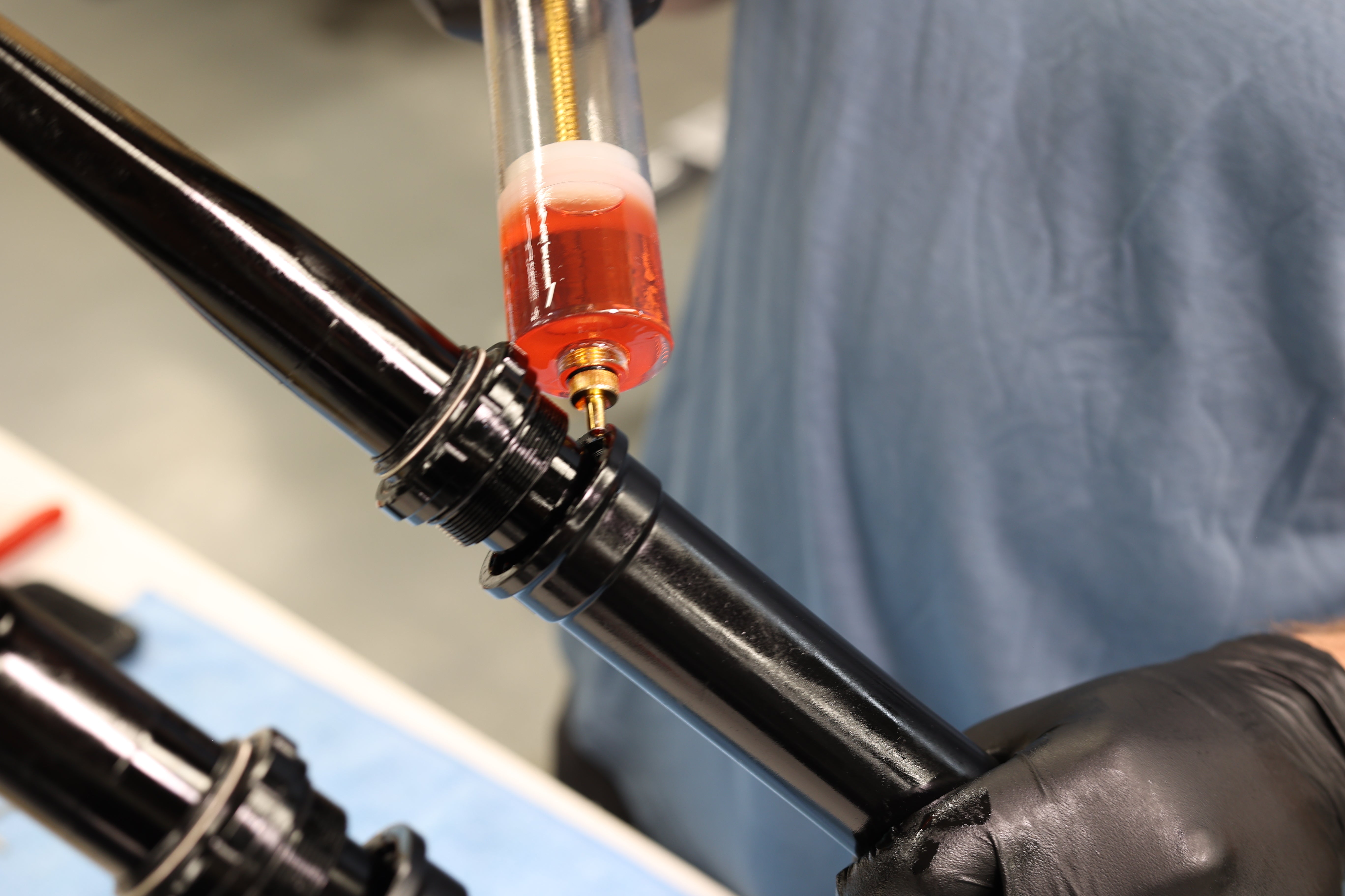
Secure fork with legs up. Using syringe, add 10ml of 15wt Motorex Racing Fork Oil to air spring leg.
Fork Oil in Syringe
Adding Oil to Spring Side Leg
Step 3 – Seal Head Install
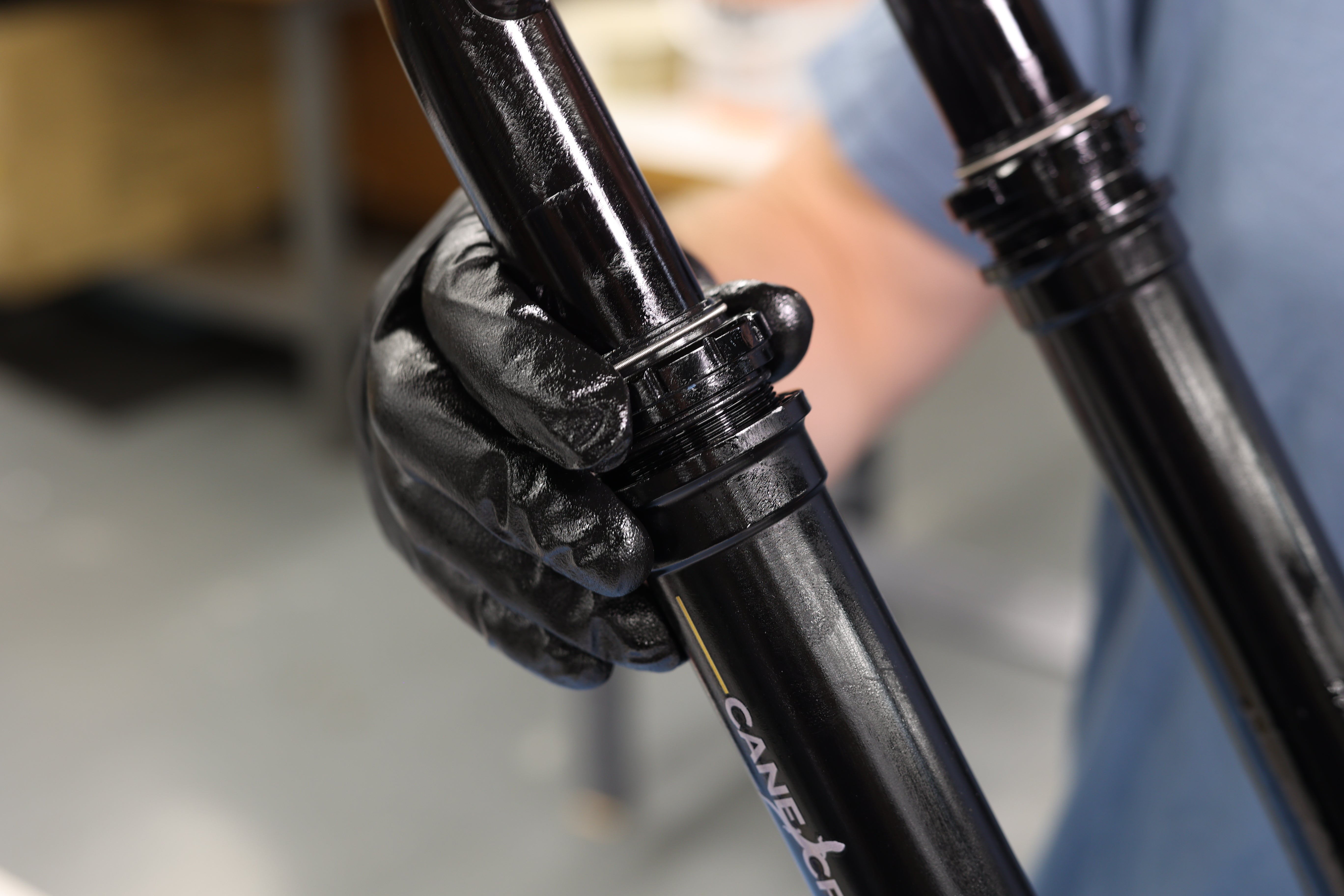
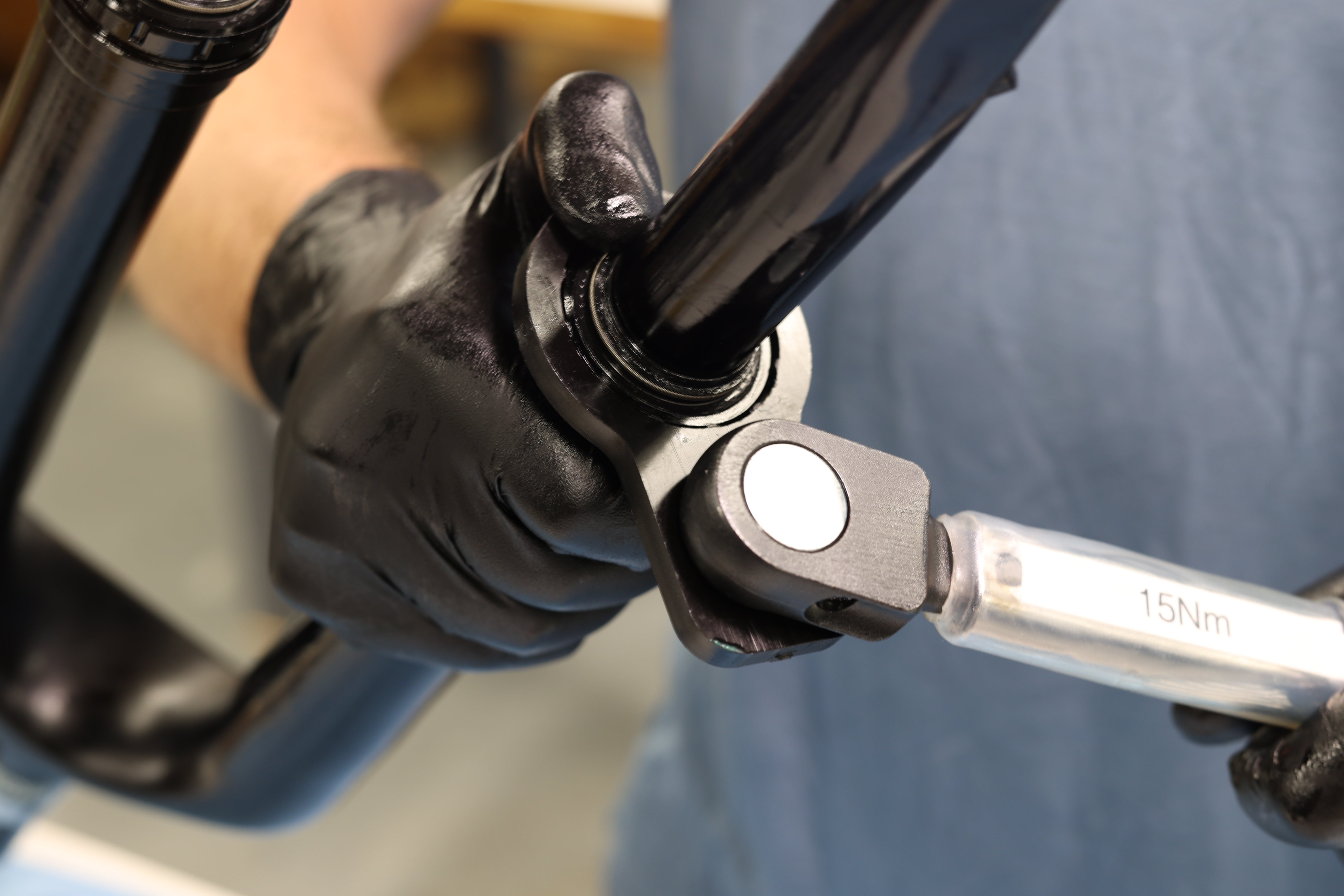
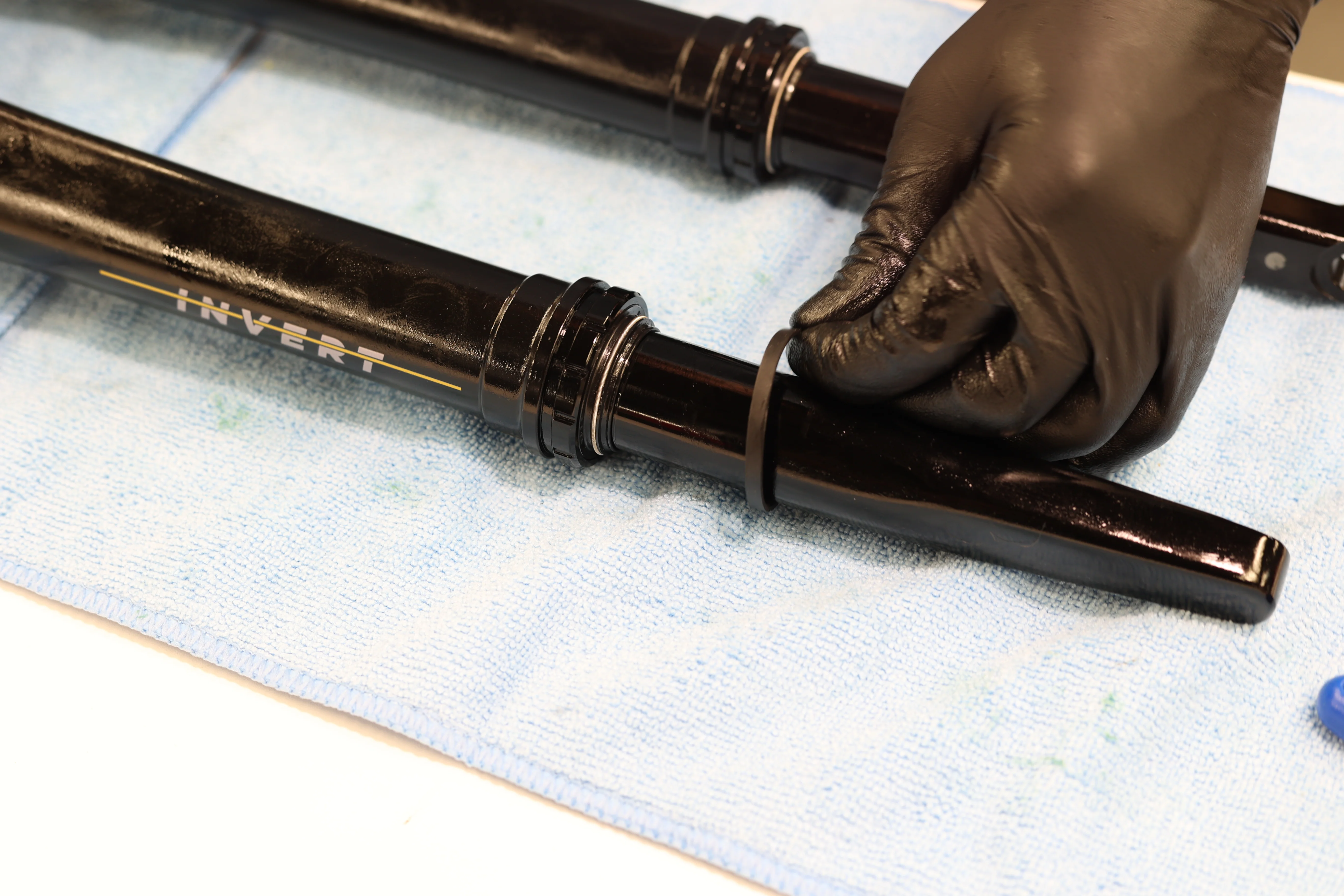
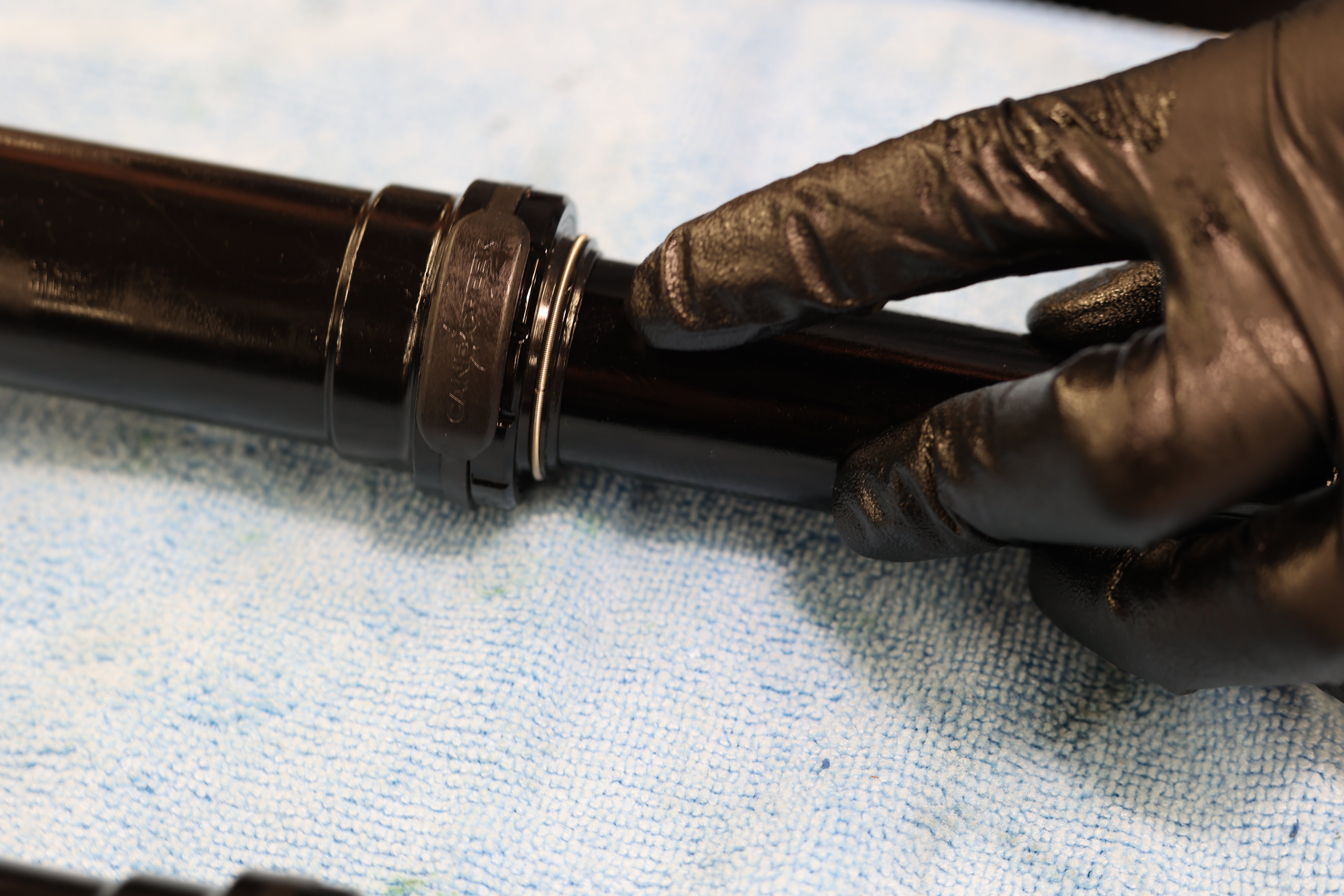
Thread lower seal heads onto fork upper. Using Bottom Bracket Tool, torque to 15 Nm. Reinstall seal head guards. Make sure they are properly seated and aligned.
Seal Head Install
Seal Head Torque
Seal Head Guard Install