
Invert Enduro User Manual
Safety Warning Information
The Cane Creek Invert Enduro fork requires a unique set up. Follow all information in this article for proper function and safety.
Installation and service of Cane Creek products require specific bicycle tools, supplies, and knowledge. All Cane Creek products should be installed and serviced by a qualified bicycle service technician, in accordance with Cane Creek specifications. Improperly installed, serviced, and maintained products can fail, resulting in SERIOUS INJURY OR DEATH.
Setup and configurations vary greatly between bicycle manufacturers. Carefully read this manual and your bicycle’s owner’s manual. Failure to follow the items outlined in these manuals, including but not limited to installation procedures, warnings, Nm torque specifications, maintenance requirements, service intervals, and/or modifications, could lead to damage, causing loss of control of the bicycle and resulting in SERIOUS INJURY OR DEATH.
DO NOT attempt to force parts to fit. Confirm compatibility before installation and use. DO NOT disassemble, modify, or use aftermarket parts with/or to repair Cane Creek components. Doing so may cause damage to the component or bicycle which could lead to loss of control of the bicycle and result in SERIOUS INJURY OR DEATH.
Each time, before you ride, be sure all components are installed correctly, tightened to specifications, and you are familiar with how your bicycle and Cane Creek components operate. Components that are out of adjustment, improperly installed, or are not used properly, can cause loss of control of the bicycle and result in SERIOUS INJURY OR DEATH.
All components on a bicycle, including Cane Creek components, should be inspected, and adjusted at periodic intervals and after a crash or fall. Inspect the exterior for wear or damage, inspect for correct torque settings, and listen for unfamiliar noise. If any damage is noticed, stop using and contact your local dealer or Cane Creek directly.
A broken or malfunctioning fork may cause loss of bicycle control and result in SERIOUS INJURY OR DEATH. If the fork ever loses oil, air or makes unusual noises, stop riding and have the fork inspected by a Cane Creek Authorized Suspension Service Center or call the Cane Creek Customer Service Team. Follow service maintenance recommendations. Fork service should be performed by Cane Creek Cycling Components or a Cane Creek Authorized Suspension Service Center. Visit www.CaneCreek.com or contact us at 828-641-9560 to locate a Cane Creek Authorized Suspension Service Center or for the most up to date service procedure revisions.
Required Tools
Torque wrench (3mm & 6mm hex bits)
3mm hex
6mm hex
Hacksaw with metal-cutting blade
Saw guide
Star nut setting tool
Zip ties
Assembly grease
Shock pump
Additional Tools (see conditions)
Brake caliper adapter (for rotors larger than 200mm)
13mm socket (for volume reduction)
Fork Features Overview
| Hub Spacing | 110mm Boost | 15mm or 20mm Axle |
| Brake Mount | Post Mount | 200mm Minimum Rotor - Larger w/ Adapter |
| Offset | 44mm | — |
| Axle-to-Crown | 576mm | 586mm | 596mm | 160mm Travel | 170mm Travel | 180mm Travel |
| Tire Clearance | 29 x 2.6" | — |
| Brake Hose | Up to 5.5mm diameter | - |
| Steerer Tube | 1 1/8" - 1 1/2" | 28.6mm - 40mm |
| Air Pressure | 150psi MAX | — |
| Recommended Sag | 25% | Sag Notches on Air Side Guard |
| Low Speed Compression | 10 Clicks | Factory Neutral: 5 |
| High Speed Compression | 10 Clicks | Factory Neutral: 5 |
| Rebound | 10 Clicks | Factory Neutral: 5 |
| Volume Reduction | 8 Positions | Factory Neutral: 1 of 8 (8 = MAX progressive) |
Torque Specs
| Part | Torque Spec |
|---|---|
| Main Axle Bolt | 13.5 Nm max |
| Axle Pinch Bolts | 4 Nm |
| Bleed Screws | 1-2 Nm |
Fork Prep & Install


Step 1 – Install Crown Race
Lightly grease the steerer tube.
Install a crown race compatible with your bike's headset according to the headset manufacturer's instructions.


Step 2 - Cut Steerer Tube
Insert fork in frame with crown race and headset in place.
Slide chosen headset spacers and stem onto steerer.
Mark steerer tube and cut steerer using fine-tooth, metal hacksaw blade and saw guide.
MEASURE TWICE, CUT ONCE!


Step 3 - Install Star Nut
Use a star nut setting tool to drive star nut into steerer to a depth of roughly 15mm.
Air Seal Head Wrench on Air Seal Head


Step 4 - Stem Installation & Headset Preload
Slide fork into frame with headset in place.
Install headset top cap, spacers, and stem onto steerer tube.
Preload headset to 3Nm using preload bolt and tighten stem bolts to manufacturer-recommended spec.
WARNING: Do not install more than 30mm of spacers below the stem. It is also ideal to have the steerer extend several mm past the top of the stem and use one 5mm or 10mm spacer on top of stem to ensure proper stem clamping force.
Front Brake & Hose Guide Install


Step 5 – Brake Caliper Install
Invert Enduro's post mount is native to 200mm rotors; rotors larger than 200mm require the appropriate adapter.
Install brake caliper according to the brake manufacturer's instructions.
Attach the front brake hose to the SideSwipe guard using zip ties. Be sure the zip ties are seated in their notches and the hose is held firmly against the inside edge of the hose keeper tab.
If necessary, adjust the caliper banjo bolt so the hose makes a clean arc and does not contact the rotor, fork leg, guard, or other parts.
Install caliper
No adapter needed for 200mm rotors
Use an adapter for 220 / 223 rotors
Note position of hose against 'keeper' tab
Adjust banjo fitting if necessary
Adjust banjo fitting if necessary


Step 6 - Hose Guide Install
Pop brake hose guides over brake hose and position them within the yellow dotted lines on the Cane Creek decal.
Loosely zip-tie the guides so they stay in place but can still be adjusted and rotated to keep the hose on a smooth, consistent path clear of the rotor, tires, and other parts.
Leave the guides loose until the front wheel is installed, then compress the fork to check the hose path through full travel. Once satisfied, tighten the zip ties fully to prevent slipping.
Snap guide around hose
Clip guides on to fork
Zip tie passes through guide
Guide lines up with dotted yellow line
Axle Install
Invert Enduro can be used with a 15mm or 20mm SquareLoc axle.
The SquareLoc axle uses a floating, self-extracting design whereby the axle fixing bolt is captured in the dropout and pushes the axle out as it is loosened. Invert Enduro’s inverted design can allow for the legs to rotate/compress independently without the axle installed. To aid in installation of the wheel, try not to twist, pull, or push either fork leg when the axle is removed. If the legs become misaligned, try to realign by hand as best as possible before installing wheel. It is often easiest to remove and install the axle with the bike upside down.
WARNING: An improperly aligned, installed and tensioned axle, could result in disengagement of the axle and possibly causing serious injury or death.


Step 7a – 15mm Axle Removal
While not critical, we highly recommend turning the bike upside down for easiest axle removal & install. Make sure that cockpit controls, levers, buttons, accessories are not contacting the ground in such a way that would damage them.
Loosen all pinch bolts thoroughly, so that there is a visible gap between bolt heads and dropout flange.
Remove the axle by turning the axle fixing bolt counterclockwise with a 6mm hex. This is a captured bolt that is meant to be held within the dropout. The self-extracting design will push the axle out the other side of the fork. While unthreading this bolt, hold pressure with one hand on the air side to prevent the legs from spreading apart. If axle binds, you can gently push on axle bolt to help push axle out.
Make sure the 15mm axle adapter stays in the brake side dropout. The slot in the axle adapter should line up with the slot in the dropout.
Watch the video
Upside down
Loosen pinch bolts FULLY
Pressure with opposite hand
15mm axle adapter


Step 7b – 15mm Axle Install
Lightly grease the ends of the axle and make sure dropouts are wiped clean.
Install the wheel into the dropouts and insert axle. Make sure 3mm hex tool lines up with notch in air side dropout. Due to SquareLoc axle design, the axle may find considerable resistance when being inserted. Gently rock fork dropouts back and forth to be sure fork legs are perfectly aligned.
Begin to tighten axle fixing bolt, making sure there is smooth engagement of the threads. If you feel resistance - STOP - realign legs and start again so as to not damage threads.
FOLLOW THIS SEQUENCE EXACTLY to ensure proper leg alignment and performance:
1: Torque the axle to 13.5Nm
2: Torque the two brake side pinch bolts to 4Nm, alternating between bolts every several turns to keep even torque on both.
3: Compress the fork sharply several times to ensure the air side leg is aligned. The air side dropout is not meant to contact the hub endcap. Look for 1-2mm of axle exposed inside of the air side dropout. This indicates proper alignment.
4: Torque the two air side pinch bolts to 4Nm, alternating between bolts every several turns to keep even torque on both.
Gently rock while inserting axle
Step 1: Torque axle fixing bolt
Step 2: Torque brake side pinch bolts
Step 3: Compress fork sharply
Air side dropout should not contact hub end cap. Several mm of axle should be showing.
Step 4: Torque air side pinch bolts
WARNING
It is critical that this order of operations be followed precisely. Failure to properly align and pinch axle can result in diminished fork performance.

Step 7c – 20mm Axle Install
While not critical, we highly recommend turning the bike upside down for easiest axle removal & install. Make sure that cockpit controls, levers, buttons, accessories are not contacting the ground in such a way that would damage them.
Remove the 15mm axle using instructions from step 7a.
Remove the 15mm axle adapter from the brake side dropout.
Lightly grease the ends of 20mm axle and make sure dropouts are wiped clean.
Install the wheel into the dropouts and insert axle. Due to SquareLoc design, the axle may find considerable resistance when being inserted. Gently rock fork dropouts back and forth to be sure fork legs are perfectly aligned.
Begin to tighten axle fixing bolt, making sure there is smooth engagement of the threads. If you feel resistance - STOP - realign legs and start again so as to not damage threads.
FOLLOW THIS SEQUENCE EXACTLY to ensure proper leg alignment and performance:
1: Torque the axle to 13.5Nm
2: Torque the two brake side pinch bolts to 4Nm, alternating between bolts every several turns to keep even torque on both.
3: Compress the fork sharply several times to ensure the air side leg is aligned. The air side dropout is not meant to contact the hub endcap. Look for 1-2mm of axle exposed inside of the air side dropout. This indicates proper alignment.
4: Torque the two air side pinch bolts to 4Nm, alternating between bolts every several turns to keep even torque on both.
Watch the video
Turn bike upside down.
Remove 15mm axle adapter.
Install wheel and 20mm axle, rotating and massaging leg alignment to prevent axle binding.
Step 1: Torque axle bolt to 13.5Nm.
Step 2: Torque brake side pinch bolts to 4Nm.
Step 3: Sharply compress fork several times.
Make sure severl mm of sxle are showing inside of air side dropout.
Step 4: Torque air side pinch bolts to 4Nm.
Air Spring Setup
Setting sag is the most critical part of fork setup - always set (or check) it before adjusting the damper.
Cane Creek recommends 25% sag as a starting point for Invert Enduro. Use the notches on the back edge of the air side SideSwipe guard to aid in setting sag.
Setting Sag


Step 8 – Sag
Fully remove the bleed screws on top of both fork legs to release any trapped air pressure. Reinstall and tighten to 1-2Nm.
Remove the air cap on the bottom of the air side leg.
Set initial pressure to 45% of your body weight in lbs (PSI), including riding gear.
Compress the fork slightly five times to equalize the air spring. Do this again with every pressure adjustment.
Dressed in full riding gear, mount bicycle on flat ground. Bounce the fork to ensure it moves freely. Come to a rest in a standing ride position with elbows bent. Have a partner slide sag o-ring up to contact the wiper seal at your sag position.
Dismount the bicycle carefully so as not to move the o-ring from its position.
Visually check position of o-ring relative to sag notches. Each notch represents 25% sag for each travel.
Add or remove air pressure in 5 PSI increments to dial in sag amount. If more sag is needed, remove air. If less, add air. Be sure to cycle the fork several times each time you adjust the pressure.
Remove bleed screws
Must be fully removed to bleed chassis
Weight (lbs) x 0.45 = starting pressure (PSI)
Compress fork to equalize spring
Partner slides o-ring up to meet wiper seal
Check sag using indicating notches
Suggested sag points for each travel
Air Volume Adjustment
Reducing volume in an air spring adds more support in the latter part of the stroke, greatly increasing bottom out resistance. If sag is set properly, but you are experiencing frequent, harsh bottom outs, a reduction of volume should be performed. This should be done BEFORE using compression damping to mitigate bottom outs. If you are not experiencing harsh bottom outs, there is likely no need to perform volume reduction. Too much volume reduction (a.k.a. progression) intensifies big hits and can limit your ability to use full travel.
WARNING: When adjusting volume, be sure to remove ALL air pressure from air spring. Failure to properly do so can result in a dangerous decompression event.


Step 9 – Air Volume Adjustment
Remove all air pressure from the fork.
Using a 13mm socket, remove the air valve assembly.
Unthread the black air volume piston wingnut.
Slide gold volume piston up 1 notch on the shaft, away from air cap. Make volume adjustments in single notch increments, then ride and reevaluate if more is needed. One position of air volume adjustment makes a notable difference in bottom out resistance.
Retighten black wingnut to secure piston.
Confirm that the system is clean and lightly greased, including the threads and o-rings. Reinstall air valve assembly, torque to 36Nm, and follow step 8 to re-set sag.
Release air pressure
Remove air valve (13mm socket)
Remove entire assembly
Loosen wingnut
Slide gold piston to next notch
Grease o-rings & threads
Reinstall air valve assembly
Damper Adjustment
The damper in your Invert Enduro fork helps control the overall motion, behavior, and attitude of the fork. All Cane Creek forks are shipped with a Factory Neutral Tune, with all damper adjusters set to the middle of their ranges. These should be considered your ‘neutral’ settings. They represent a balanced and well-rounded tune that will work nicely for most riders. Make sure your fork is set to this tune before starting your specific tuning process. If you ever get lost and want to go back to neutral, these are the settings you should return to.
For in-depth, personalized guidance on damper tuning, we highly encourage using our interactive ForkTuner app.
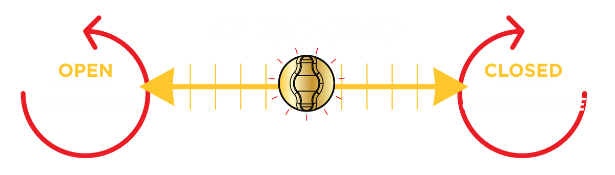
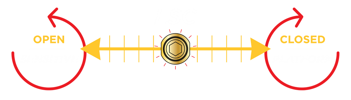
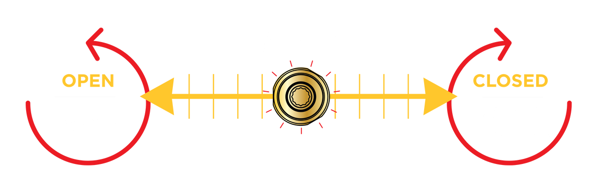

Step 10 – Rebound Damping
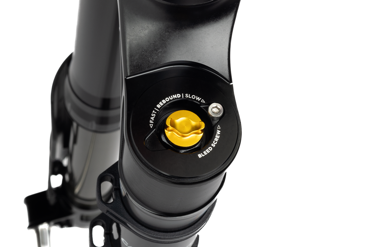
Rebound controls the speed at which the fork can extend after being compressed. In adjusting rebound, you’ll be looking for a balance between traction and liveliness (faster rebound) vs. a sense of composure and control (slower rebound).
Tune rebound first, before moving on to compression.
To adjust, turn adjuster on the top of the brake side leg labeled 'Rebound.'
Turn clockwise to increase damping. (slower fork return speed)
Turn counterclockwise to decrease damping. (faster fork return speed)
See graphic above for Rebound adjustment characteristics.


Step 11 – Compression Damping
Compression damping controls how easily the fork compresses under impacts and rider inputs. It controls how supportive and firm the suspension feels. Tune it after you've arrived at a satisfactory rebound tune.
Start with both adjusters set to the middle of their range. This is your 'neutral' setting and represents a balance of all desirable traits for most riders. If you're not sure what you prefer, this balanced mid-tune is a perfect place to return to.
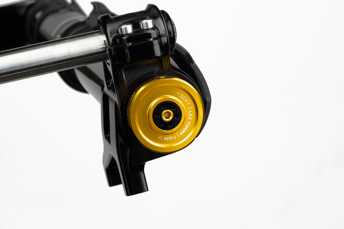
LSC - Low-Speed Compression
- Controls how fast/easily the fork compresses during pedaling, pumping, and pushing the bike through turns and compressions. This controls the overall sense of firmness and is used to help dial in a supportive platform for the rider to lean on/push against.
To adjust, use the 3mm hex hidden in the end of the axle. Turn clockwise to increase damping (more platform), turn counterclockwise to decrease damping (less platform).
HSC - High-Speed Compression
Controls how fast/easily the fork compresses from severe & abrupt impacts (tall roots, square-edged rocks, braking bumps). In adjusting HSC, you will try to determine if the front wheel is moving freely enough over these features or if you need more support to push through them.
To adjust, turn the large, gold HSC adjuster by hand. Turn clockwise to increase damping (more impact support), turn counterclockwise to decrease damping (more plushness).
Service
Recommended Procedures & Intervals
| Procedure | Every Ride | Every 5 Rides | Every 50 Hrs | Every 100 Hrs/Annually |
|---|---|---|---|---|
| Clean and inspect fork exterior, including travel indicating o-ring. Wipe clean. | X | - | - | - |
| Inspect stanchions for scratches, dents, or other damage. Wipe stanchions and wiper seals clean. | X | - | - | - |
| Inspect and clean air valve threads and surrounding area to prevent dirt from entering air spring during inflation. | X | - | - | - |
| Check sag and fork extension. (reaching full travel) Reset air pressure. | - | X | - | - |
| Open bleed screws to remove trapped pressure from uppers. | - | X | - | - |
| Inspect headset preload, brake caliper connection, and axle torque. | - | X | - | - |
| Remove legs, clean and inspect bushings, drain dirty splash oil and replenish. | - | - | X | - |
| Full air spring and damper rebuild performed by Cane Creek Authorized Service Center. | - | - | - | X |
WARRANTY INFORMATION
LIMITED TWO (2) YEAR WARRANTY ON SUSPENSION PRODUCTS
Subject to the limitations, terms and conditions hereof, Cane Creek warrants, to the original retail owner of each new Cane Creek suspension product, that the Cane Creek suspension product, when new, is free from defects in materials and workmanship. This warranty expires two (2) years from the date of the original Cane Creek suspension product retail purchase from an authorized Cane Creek dealer or from a Cane Creek authorized Original Equipment Manufacturer where Cane Creek suspension is included as original equipment on a purchased bike, unless otherwise dictated by requirement of law.
TERMS OF WARRANTY
This warranty is conditioned on the Cane Creek suspension product being operated under normal conditions and properly maintained as specified by Cane Creek. This warranty is only applicable to Cane Creek suspension purchased new from an authorized Cane Creek source and is made only to the original retail owner of the new Cane Creek suspension product and is not transferable to subsequent owners. This warranty is void if the Cane Creek suspension product is subjected to abuse, neglect, improper or unauthorized repair, improper or unauthorized service or maintenance, alteration, modification, accident or other abnormal, excessive, or improper use. Should it be determined, by Cane Creek in its sole and final discretion, that a Cane Creek suspension product is covered by this warranty, it will be repaired or replaced, by a comparable model, at Cane Creek’s sole option, which will be conclusive and binding.
Cane Creek components are designed for use only on bicycles that are pedal powered or pedal assisted.
This limited warranty does not apply to normal wear and tear, malfunctions or failures that result from abuse, neglect, improper assembly, alteration or modification, improper or unauthorized repair or maintenance, crash, accident or collision, or other abnormal, excessive or improper use.
Wear and tear parts are subject to damage as a result of normal use, failure to service according to Cane Creek recommendations, and/or riding or installation in conditions or applications other than recommended.
Wear and tear parts include:
• Air sealing O-rings
• Bearings
• Bottom out pads
• Bushings
• Corrosion
• Dust seals
• Foam rings, Glide rings
• Rear shock mounting hardware and main seals
• Rubber moving parts
• Stripped threads/bolts (aluminum, titanium, magnesium or steel)
• Lower tubes (stanchions)
This warranty shall not cover damages caused by the use of parts of different manufacturers or parts that are not compatible or suitable for use with Cane Creek components.
THIS IS THE EXCLUSIVE REMEDY UNDER THIS WARRANTY. ANY AND ALL OTHER REMEDIES AND DAMAGES THAT MAY OTHERWISE BE APPLICABLE ARE EXCLUDED, INCLUDING, BUT NOT LIMITED TO, INCIDENTAL OR CONSEQUENTIAL DAMAGES OR PUNITIVE DAMAGES.
To the extent allowed by local law claims under this warranty must be made during the warranty period and within one (1) year following the date on which any such claim arises.
When making a claim under this Limited Warranty you will be required to provide to an authorized Cane Creek Warranty Center:
1. The Product (or the affected part) and
2. A copy of the original proof of purchase, which clearly indicates the name and address of the seller, the date and place of purchase, the product part number and if utilized, a serial number. If Cane Creek products are sold as part of a complete bicycle, the bicycle brand, model, model year, and serial number should be included.